Friday, November 29, 2013

WEEK 9

Title : Literature Review

Introduction

At week 9, the study focused on a literature review of existing projects that have been in the market. This study is important, to ensure that project will be built on the right track, so that, it does not depart from the original objectives of the project. Results from this study will be used to improve project microcontroller-based egg incubator, in order to complete a project eggs incubator  better than before.

Objective
  1. To gather information from the existing project as a reference.
  2. To study about eggs incubator control system using microcontroller and other devices.

Project Encountered

This week, more study on literature reviews as reference material and to add the idea in designing the project. Actually, none of the problems encountered in this review, because it is just knowledge / guidance in developing an incubator project, so do not much of a problem encountered during the completion of microcontroller based projects egg incubator

Project Description

There are many egg incubators at market nowadays. They come with several features that differentiate their product with other. However, they use the same principle in creating their product. For example, Automatic Forced-Air Incubator  uses a light bulb to increase the temperature in the incubator, while, Mini Eco Eggs Incubator , uses heater coil for the same purpose. In this project, smart incubator makes the other eggs incubator as literature review in order to provide an automatic eggs incubator at low cost and easy to handle.
Below is 2 example existing project to be the reference :-


  • Automatic Forced-Air Incubator

Automatic model with a capacity / load the eggs of 100 eggs, also can accommodate nearly 300 quail eggs. For operating an automatically diverting eggs for up to 8 times a day by the installation of electric motor, timers and relays. Using a thermostat brand products Caemz Italy known for its precision control of temperature up to 1 degree Celsius, clear digital thermometer displays the temperature of incubator operation, the blower fan is temperature resistant and moisture and heat lamps are easily replaced with 5 watt, low and save electricity.
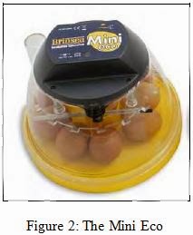


  • The Mini Eco

The Mini Eco holds 10 hens‟ eggs (or equivalent) and provides the fine temperature control to ensure consistent and reliable hatches. Temperature is monitored on a purpose built liquid-in-glass thermometer and although factory set, the electronic temperature control allows fine tuning of the temperature setting if required.


Project Outcome

Based on studies and observations that have been performed on two example project that Automatic Forced-Air Incubator and The Mini Eco. There are some advantages and disadvantages on both of this project. Therefore, all the advantages of existing projects will be used and any deficiencies will be corrected/improved. Below, there is little information about the features of the project to be developed and the project is already available in the market today.


Tuesday, November 26, 2013

WEEK 8

Title : Block diagram of project

Introduction 

The block diagram is created to identify the inputs and outputs that will be used in the project. It consists of a combination of all of the problems encountered and the information obtained from research with the best solution for the purpose. Block diagram is a diagram of a system in which the parts or functions are represented by block of connected the lines that show the relationship the block. At the end of this section, a complete block diagram.

Objective

  1. To design the block diagram that exactly with the required specifications for this project.
  2. To know the input and output of the project through a block diagram.
Problem Encountered

From the activities this week, it does not have much of a problem because the information used to make the best solution is from data collected before and it will not give any problem to develop a block diagram.

Project Description

The information gathered from previous research is compressed to achieve the main objective of the project is in an easy and efficient way to create an egg incubator project. Once the input and output are identified through previous studies. Thus, the result was the a block diagram for this project.

Project Outcome

The concept that will be used in Micro controller based eggs incubator is such as block diagram at figure 1 below :-


Saturday, November 23, 2013

WEEK 7

Title : Components and parts of project

Introduction 

Each project to be developed has a distinctive design. This is because of the design phase of the project is one that should be in developing the project. The purpose of the design phase of the project is to achieve the specific goals, specific tasks, and certain results, so it does not run away with the project objectives. In all the tasks for this week, it also includes a few inquiries for parts / components that will be used in the project.

Objective
  1. To design the project coincides with the main objectives of the project.
  2. To investigate the material / component / equipment that will be used throughout the project.
  3. To combine all the materials obtained according to the designed project.
Problem Encountered


Designing efficient project requires experience in certain fields and basic knowledge of other matters related to the design is required. Without these criteria, it will be quite difficult to design the project. However, with reference to the some websites it can also give you some ideas that are very helpful for designing the project according to the required design. This is because, if the design is not perfect incubator based characteristics are required will cause damage to the eggs during the hatching eggs. Design an incubator influencing the temperature and humidity in the incubator, if not taken care, it will damage the embryo in the eggs before they hatch.In the find for materials that will be used, the type of material and product specifications required in this project should be identified to prevent material from getting damaged during testing and building / fixing / circuits. However, this problem can be solved by doing a study / research is needed and record important data for used in the future.

Project Description

In designing the project some important elements should be taken. Following a few questions that should be taken into consideration in designing the project. Among them are : -
  1. What is the concept/theme of the project that want to designed?
  2. What is the type of material that suitable to used? (i.e plastic, wood, steel and etc).
  3. Project size - how large project size that needed accordance with the project criteria.
  4. What is the type of controller that want to used? (i.e u-controller - PIC16F877A,  and etc).
  5. What is the materials that needed for I/O?
  6. How much the amount of voltage/current needed for each electrical/electronics materials?
Based on the list of questions above, the concept is simple to use and compact.Type of material that will be used for the design of incubators and protect the circuit is from plastic materials. The size of the design project is small eggs incubator for easy to control the temperature inside the incubator and simple to change places.In term of their controller, PIC 16F877A - Main Board will be used as circuit controller.Why PIC16F788A to make it the first choice as a controller circuit in the project? It is because cheaper and one a simple way to control circuit includes a code of their programs. Moreover, to practice what has been learned in the introduction of micro controller subject to the project.

Below is the materials that will be used for I/O and the additional materials including with the specifications for each materials will be listed such below:-

List of materials:

Hardware

  1. PIC 16F877A 
  2. Power supply 12V
  3. LCD Display
  4. LED
  5. Torque motor 
  6. Push button
  7. Limit switch
  8. Light bulb
  9. Casing
  10. LM35 sensor
  11. Various size single core of cable/wire
  12. Soldering tool kit
  13. Capacitor,resistor,transistor,diode and etc.
  14. Op-amp (LM 741)
  15. Voltage regulator +5V
  16. Relay
  17. Mosfet IRFZ46N

Software 

  1. PIC16F877A

Project Outcome

As a result of the project, the concept / theme of the project design that will be used is simple and compact design that coincides with the main objectives of the project .From the figures below show the picture of PIC16F877A, pin configuration and specification :-


Monday, November 11, 2013

WEEK 6

Title : Flow chart

Introduction

In each project should have its own flow charts. This is to describe the function or movement of a project. Therefore, the design phase of the project is one that should be in developing the project. The purpose of the design phase is to achieve the project with specific goals, specific tasks, and specific results. More specific, the better, which is more in line with the objectives of traditional teaching, the better. In all the tasks for the week, it also includes a few inquiries for parts or components to be used in this project.

Objective
  1. To define some of important elements that need to be applied in the design flow chart.
  2. To understand the process of project through a flow chart are designed.
Problem Encountered

The flow chart is one of the important parts that need to be known and provided that when developing a project. In the process of completing the flow chart there is some difficulty in making especially in terms of flow charts to determine the appropriate flow chart symbols to be used precisely to the project. However, it was not a big problem because the problem was solved by doing some research on the web and other sources (ie those who are experienced, lecturers, friends etc.).

Project Description

To create a flow chart for the project, visio software are used because it has important information that there is a flow chart symbols in visio software for the purpose of creating a true symbol of flow charts that will be created for this project. The information obtained will be inspired to the real flow chart. Flowchart illustrations that have been created will be shown in the next topic below.

Project Outcome

For this week, the result of this task will be obtained as the figure 1 flow chart below: -

Figure 1 : The process of flow chart


Saturday, November 2, 2013

WEEK 5

Titles : LM 35 Temperature Sensor for eggs incubator project


Introduction

Last week, we made a study of the types of temperature sensors. For this week, we will study the temperature sensor can be used for micro controller based eggs incubator project. Temperature sensor suitable for this project is  lm 35 dz temperature sensor.


Objectives
  1. To compress all the information obtained from the research to make it as the best solution for a good .project.
  2. To know the characteristics of the temperature sensor lm35 dz.


Problem Encountered

From this research, it not have much of a problem as the information used to make the best solution is from data gathered before and it will not give any problem to use a temperature sensor lm35 dz type of eggs incubation project.

Project Description

Selection of temperature sensor is very important for this incubator project because it requires an precise reading of the temperature data to ensure that the temperature inside the incubator care is in good condition. This is because, the unstable temperature will damage the embryo in the egg. So, LM35 DZ is the right choice for this project based on the characteristics available on this sensor.Further, there is little explanation of the LM35 temperature sensor operation.

LM35 is a precision IC temperature sensor with its output proportional to the temperature (in oC). The sensor circuitry is sealed and therefore it is not subjected to oxidation and other processes. With LM35, temperature can be measured more accurately than with a thermistor. It also possess low self heating and does not cause more than 0.1 oC temperature rise in still air.
The operating temperature range is from -55°C to 150°C. The output voltage varies by 10mV in response to every oC rise/fall in ambient temperature, i.e., its scale factor is 0.01V/ oC.

Pin Diagram:


Why Use LM35s To Measure Temperature?

  • It's can measure temperature more accurately than a using a thermistor.
  • The sensor circuitry is sealed and not subject to oxidation, etc.
  • The LM35 generates a higher output voltage than thermocouples and may not require that the output voltage be amplified.


What Does an LM35 Do?  How does it work?
  • It has an output voltage that is proportional to the Celsius temperature.
  • The scale factor is .01V/oC
  • The LM35 does not require any external calibration or trimming and maintains an accuracy of  +/-0.4 oC at room temperature and +/- 0.8 oC over a range of 0 oC to +100 oC.
  • Another important characteristic of the LM35DZ is that it draws only 60 micro amps from its supply and possesses a low self-heating capability. The sensor self-heating causes less than 0.1 oC temperature rise in still air.
For more information about this, please click here.LM35 DZ Datasheet


Project Outcome

What can i expect when  use An LM35 is :-

  • I will need to use a voltmeter to sense Vout.
  • The output voltage is converted to temperature by  a simple conversion factor.
  • The sensor has a sensitivity of 10mV / oC.
  • Use a conversion factor that is the reciprocal, that is 100 oC/V.
  • The general equation used to convert output voltage to temperature is:
  • Temperature ( oC) = Vout * (100 oC/V)
  • So if  Vout  is  1V , then, Temperature = 100 oC
  • The output voltage varies linearly with temperature.

How do use  LM35?  
  • Here is a commonly used circuit.  For connections refer to the picture below.
  • In this circuit, parameter values commonly used are:
              -  Vc = 4 to 30v
              -  5v or 12 v are typical values used.
              -  Ra = Vc /10-6
              -  Actually, it can range from 80 KW to 600 KW , but most just use 80 KW.